The shift
Concert sound became a logistics discipline. Systems had to pack efficiently, deploy safely, cover consistently, and survive a tour while delivering studio-like control at scale.
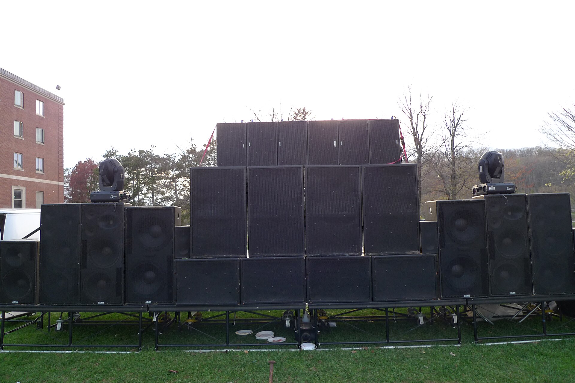
The 1980s turned custom rigs into repeatable boxes. Clair’s S-4F and R-4, Turbosound’s TMS-3, and Martin Audio’s Philishave and Modular 2 systems combined horn-loaded mids with compression-driver highs in cabinets that could be stacked or flown by the dozen. EAW’s KF850 and BH882 brought the approach to rental fleets worldwide.
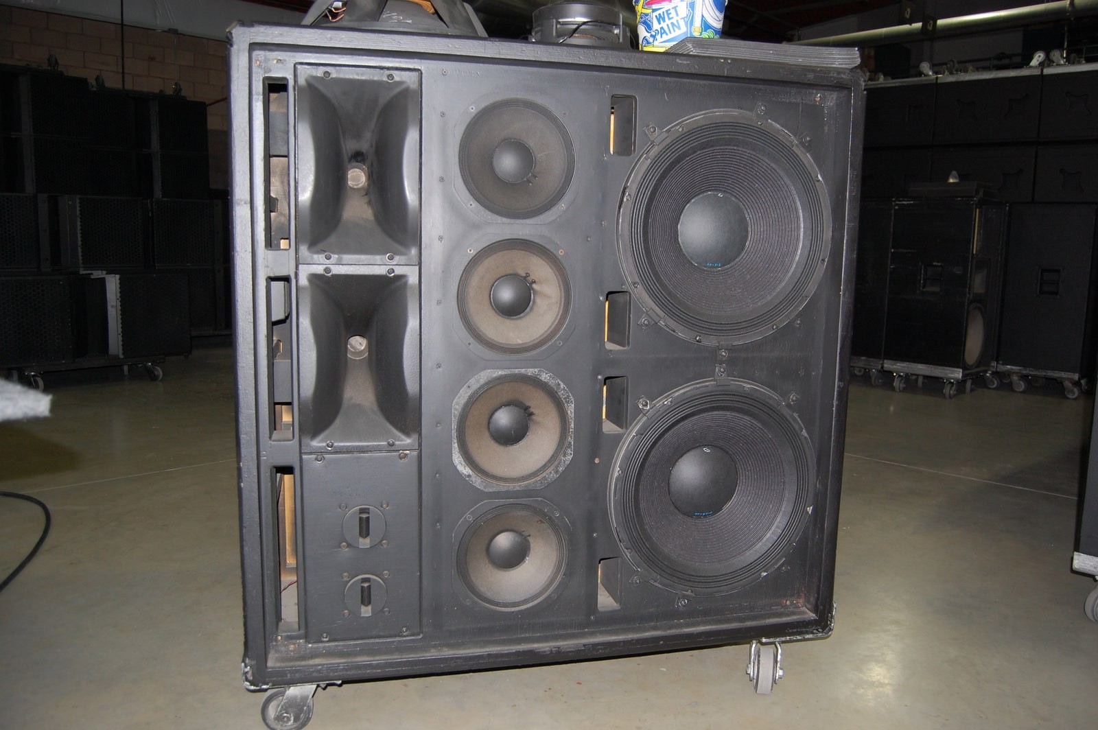 Clair Brothers S-4F© Clair Global / CLAIR Used Gear · © Clair Global; used for identification and historical commentary
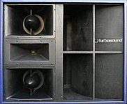 Turbosound TMS-3© Warehouse Sound Services · © Warehouse Sound Services, used for identification and historical commentary
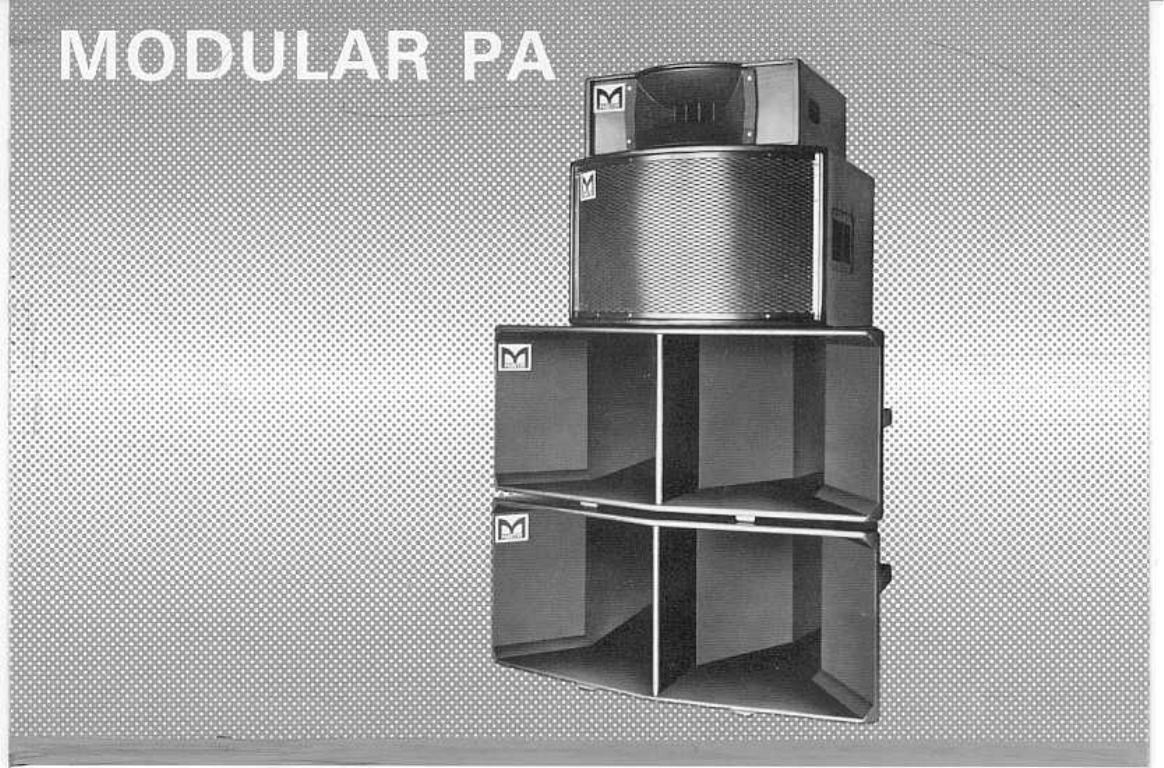 Martin Audio Philishave system© Martin Audio · © Martin Audio; used for identification and historical commentary
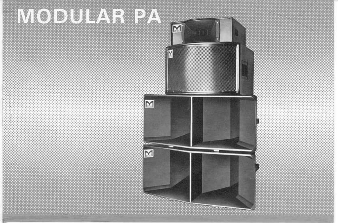 Martin Audio Modular 2 system© Martin Audio · © Martin Audio; used for identification and historical commentary
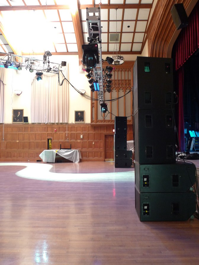 EAW KF850Kurt Snieckus · CC BY-SA 2.0
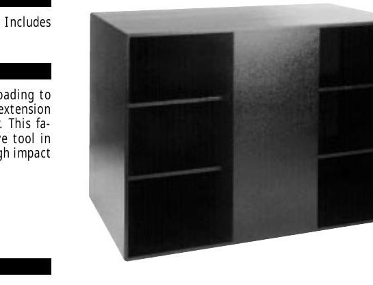 EAW BH882 bass horn© Eastern Acoustic Works · © Eastern Acoustic Works; used for identification and historical commentary
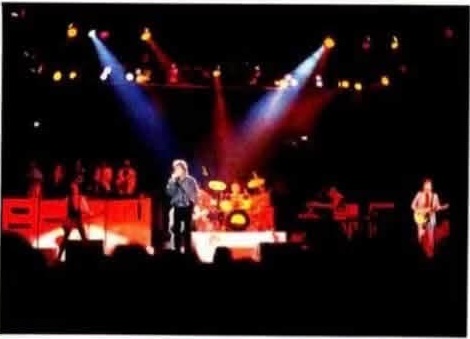
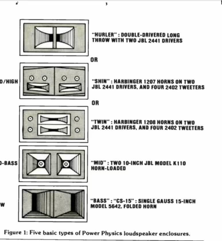
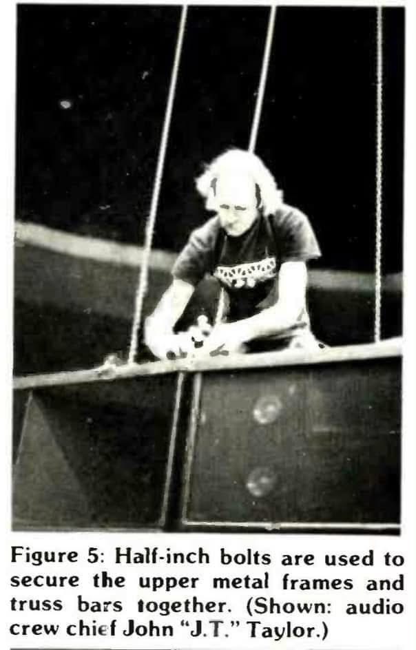
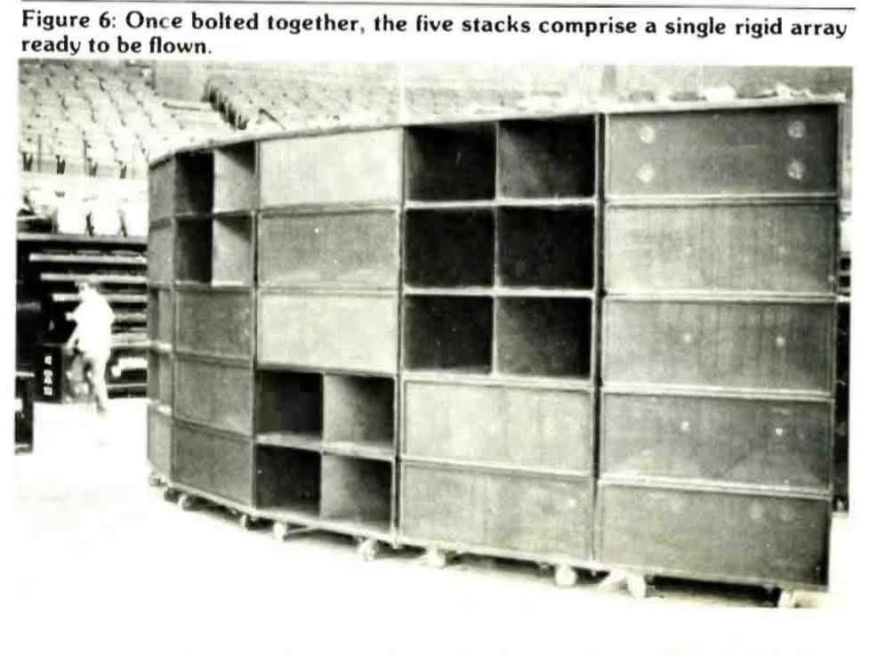
Huey Lewis and the News provide a detailed period example of that modular approach. David Scheirman’s June 1985 R-e/p report describes Sound On Stage supplying the band with its Power Physics system beginning in mid-1984. Company co-owner Jerry Pfeffer and engineer Chris Lovett developed an integrated touring package around trapezoidal, horn-loaded enclosures. Five basic cabinet types combined the CS-15 bass enclosure, with a Gauss 15-inch Model 5642 driver, a mid-bass enclosure with two JBL 10-inch K110s, and three alternative mid/high boxes: Twin, Shin and Hurler. Different horn configurations let the crew adapt coverage to each arena rather than treating every cabinet as interchangeable.
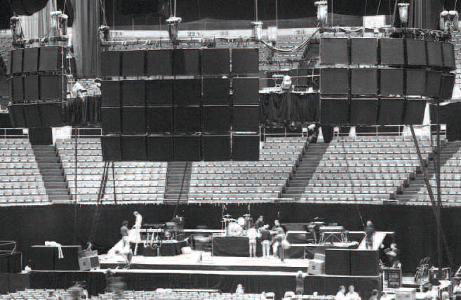
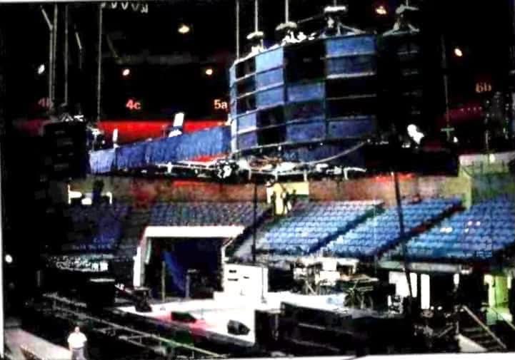
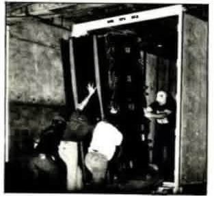
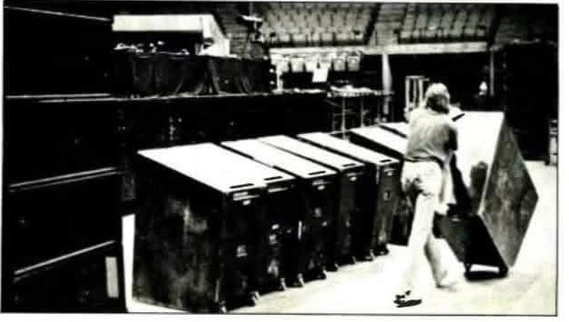
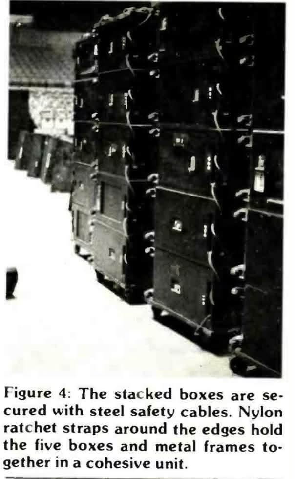
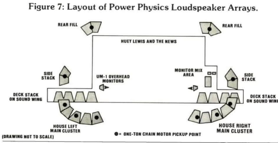
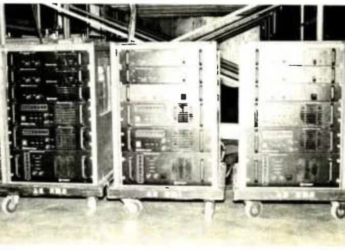
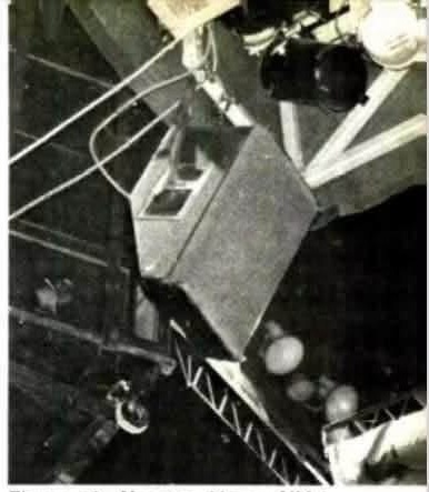
The Power Physics rig was engineered around the journey from truck to roof. Five-box stacks travelled strapped to dollies; individual cabinets had permanent wheels and an integral handle. Adjoining metal frames were bolted together, with steel safety cables and ratchet straps securing the assembly. Scheirman describes a five-stack array weighing approximately 4,000 pounds and, at the arena show he observed, a total of 102 cabinets divided between flown main clusters, rear fills, sidefills and ground-supported deck stacks. Figure 7, reproduced below from the article, records the stage layout and chain-motor pickup points. It is the original not-to-scale period drawing—not a modern reconstruction or a rigging specification for use today.
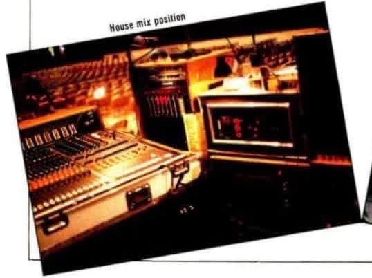
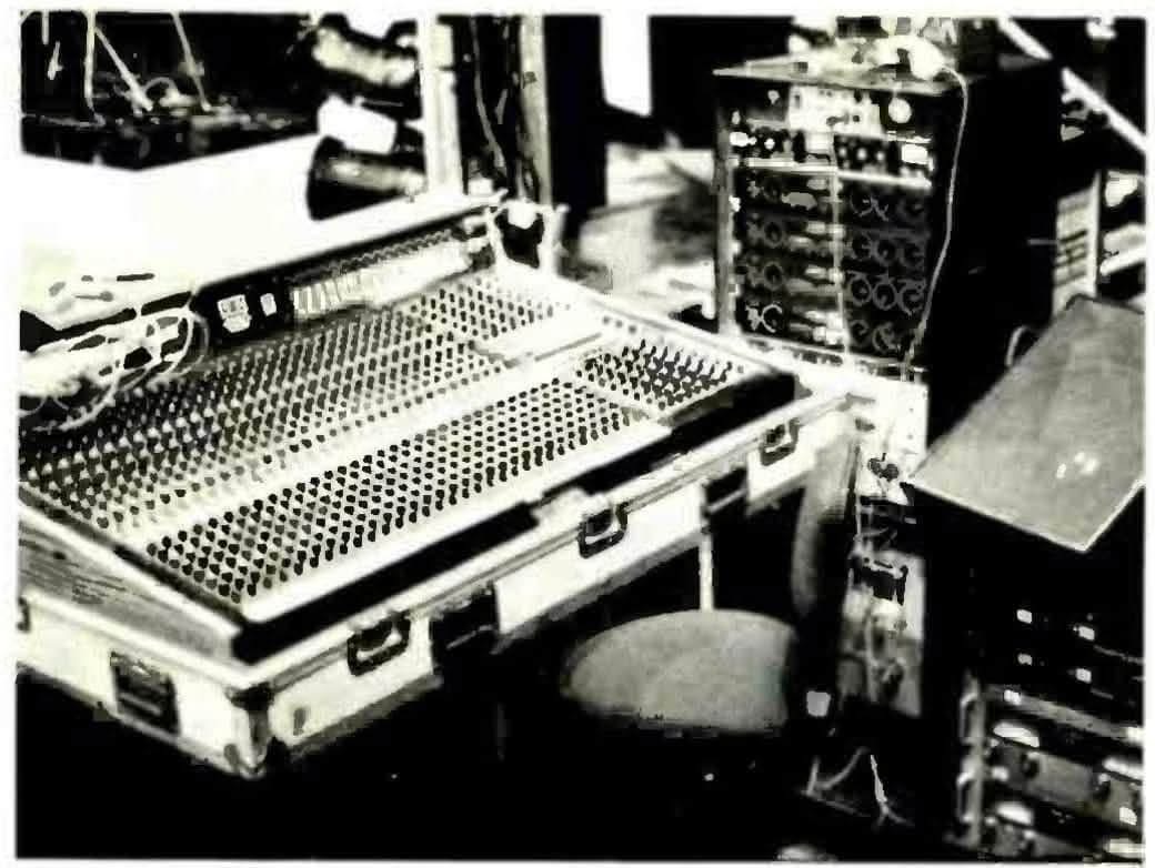
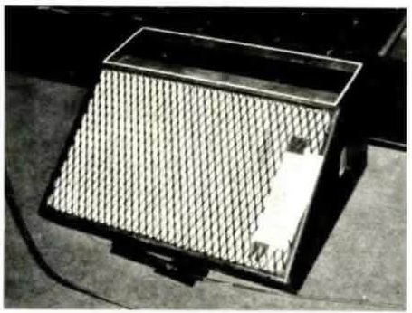
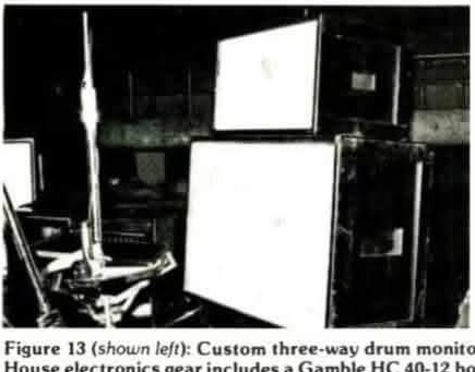
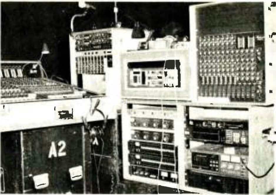
The same report shows how much of the system existed beyond the loudspeakers. Crest amplifiers powered separate frequency bands, and an Uptown Audio CO-4C four-way electronic crossover drove the Power Physics system, with a Brooke-Siren FDS-340 held as standby. Lovett describes moving from earlier three-pole Bessel filter experiments toward examining four-pole Linkwitz–Riley filters; the article does not establish that the touring crossover had already adopted the latter. Mark Deadman mixed the house sound on a Gamble desk, while Jim ‘Bugsy’ Moran used a Gamble SC 32-16 for eight monitor mixes, adding two more when the Tower of Power horn section joined the tour. A custom vocal wedge and hanging Meyer UM-1 UltraMonitors supported the stage. Deadman’s contemporary account stresses consistent sound and an affordable touring package: carrying more loudspeakers also meant another truck. Scheirman liked the show’s clarity and coverage but wanted more system headroom, making the report a useful record of both the package’s strengths and its practical limits.
Meyer Sound tied each loudspeaker to its own processor, so the MSL-3, USW-1 subwoofer and UM-1 wedge behaved predictably wherever they were hung. That approach made measurement-based tuning practical, and it pointed straight at the self-powered and line-array systems of the next decade. Electro-Voice’s HR9040 constant-directivity horn and MT-4 manifold pursued the same predictability through acoustic design. The constant-directivity horn came from D. B. ‘Don’ Keele Jr.’s horn research; Keele later received a 2002 Academy Award for Technical Achievement for constant-directivity cinema loudspeaker systems.
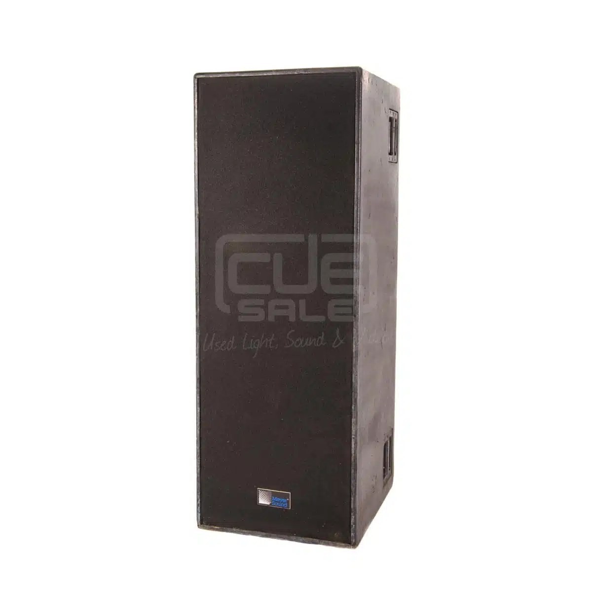 Meyer Sound MSL-3© CUE Sale · © CUE Sale; used for equipment identification and historical commentary
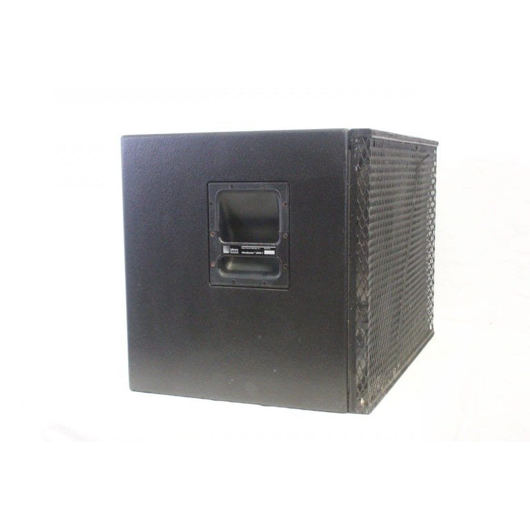 Meyer Sound USW-1 subwoofer© AVGear · © AVGear; used for equipment identification and historical commentary
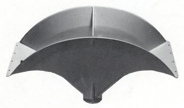 Electro-Voice HR9040 constant-directivity horn© Electro-Voice · © Electro-Voice; used for identification and historical commentary
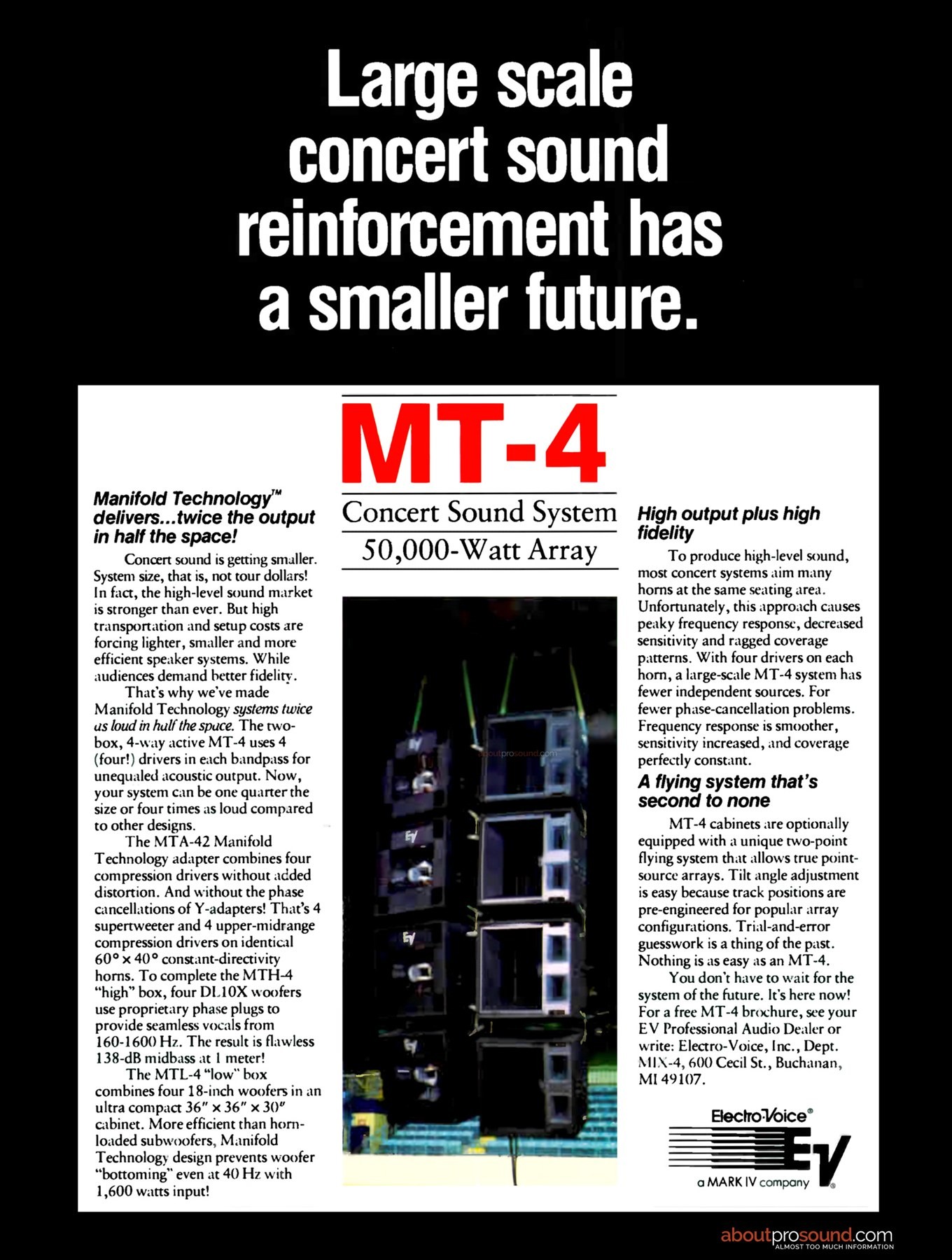 Electro-Voice MT-4 manifold system© Electro-Voice · © Electro-Voice; used for identification and historical commentary
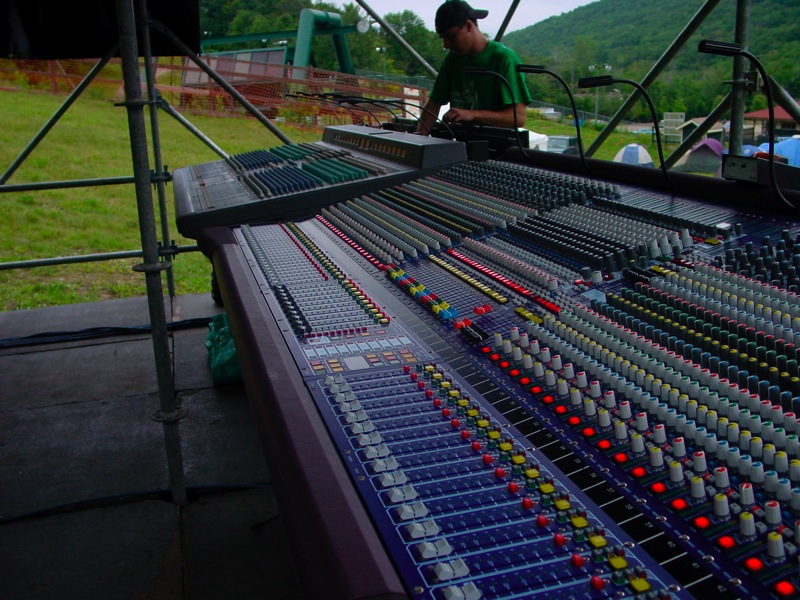
Bigger systems needed more amplifier channels and more console inputs. The Crown Macro-Tech, Crest 8001 and Lab Gruppen LAB 2000 supplied racks of reliable power. At front of house, the 1974 Yamaha PM1000 led to the late-1970s PM2000 and 1985 PM3000. The Midas PRO40, modular Soundcraft Series 800 and Series 4 offered other ways to organise increasingly large shows. More groups, aux sends and matrices meant separate control of instrument sections, monitors, effects returns and different PA zones—not merely more microphone sockets.
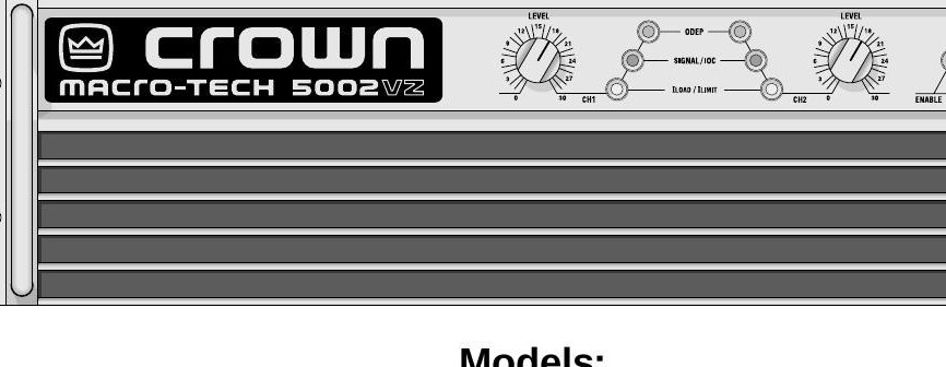 Crown Macro-Tech amplifier© Crown International · © Crown International; used for identification and historical commentary
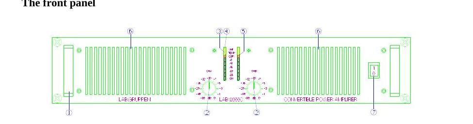 Lab Gruppen LAB 2000 amplifier© Lab.gruppen · © Lab.gruppen; used for identification and historical commentary
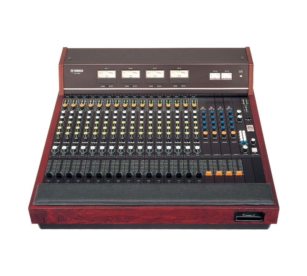 Yamaha PM1000 console© Yamaha Corporation · © Yamaha Corporation; used for identification and historical commentary
 Yamaha PM2000 console© Yamaha Corporation · Manufacturer manual cover reproduced for historical identification and commentary (fair use)
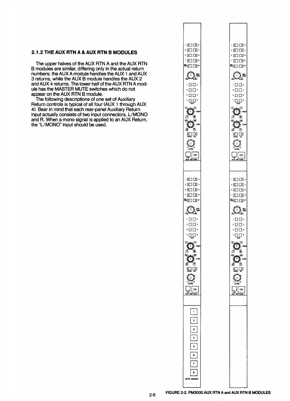 Yamaha PM3000 console© Yamaha Corporation · © Yamaha Corporation; used for identification and historical commentary
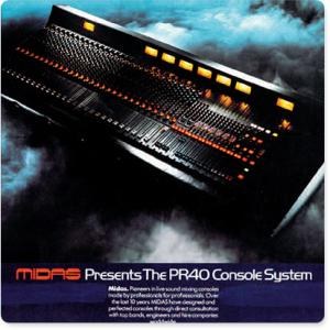 Midas PRO40 console© Theatrecrafts Backstage Heritage Collection; photographer unrecorded · Archival photograph; used for equipment identification and historical commentary
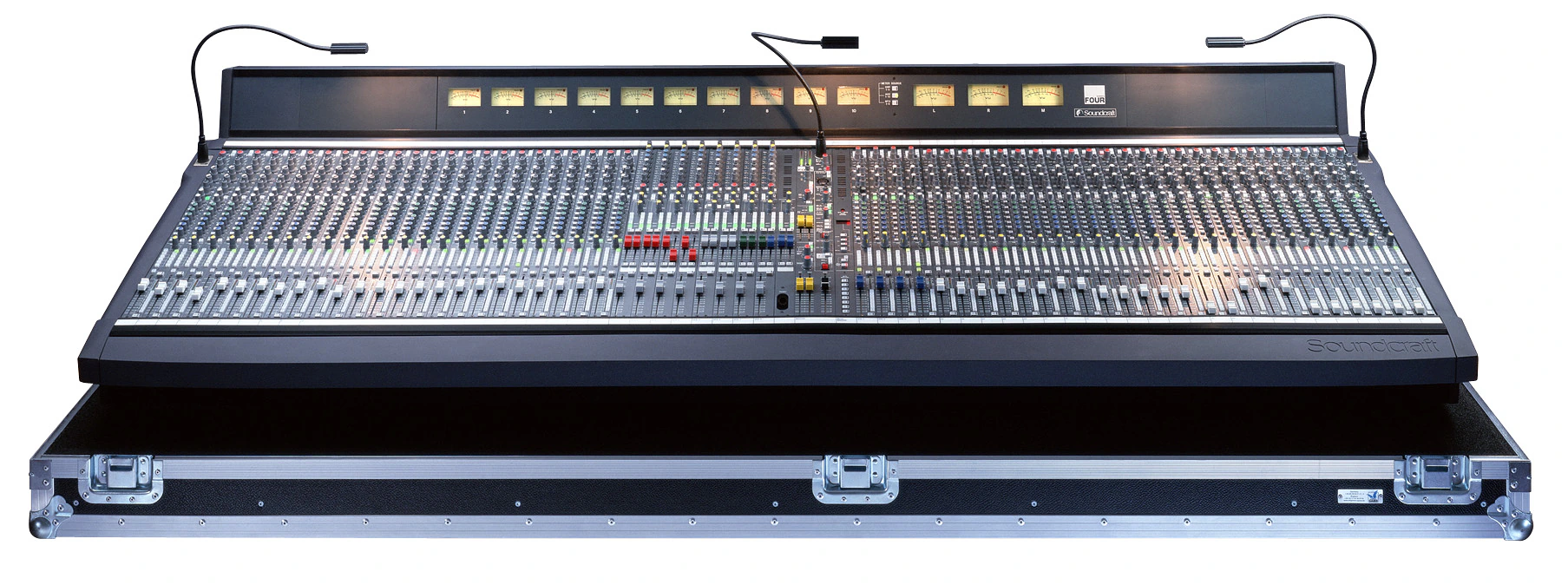 Soundcraft Series 4 console© Soundcraft / HARMAN International · © Soundcraft / HARMAN International; used for identification and historical commentary
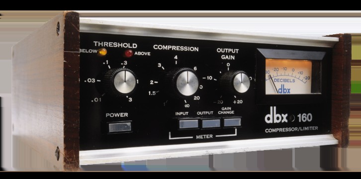
The analogue console was only the centre of a much larger control position. dbx 160 compressors occupied inserts; other rack channels supplied gates, equalisation and effects. Reverb and delay units usually received aux sends and returned to console channels, so the engineer mixed the effect as well as the dry signal. Every additional processor meant rack space, power, patching and another set of settings to document. Digital rack effects already offered programmable presets before digital consoles arrived; the later revolution was integrating processing and its recall into the whole mix, not inventing digital reverb.
The racks that hardware lived in were standardized long before touring adopted them. The 19-inch rack width with 1.75-inch unit spacing — 44.45 millimetres per U — traces to AT&T’s engineering redesign of telephone central-office racks around 1922, from which the format spread informally through telephony, broadcasting and electronics for roughly three decades. Formal standardisation lagged practice: the Electronic Industries Association’s first rack-and-panel standard appeared as C83.9-1956, was reissued as RS-310 in May 1965, and continues in the EIA-310 lineage. Why 19 inches exactly was never documented by AT&T itself; EDN’s retrospective on the rack calls the rationale folklore. Touring sound adopted the format wholesale — amplifier racks, processor racks and flight-cased shock racks — because any manufacturer’s gear then bolted into any company’s cases and rack spaces could be planned before the truck was packed.
Rigging evolved alongside the cabinets. Scaffold towers and ground stacks gave early concert crews elevated support, but modular touring truss made an overhead structure easier to transport and reassemble. Behind the Curtain's touring-history account traces a ground-supported, pre-rigged lighting truss to the Rolling Stones' 1972 tour and describes the subsequent move toward trusses flown on chain motors. That is a production-structure history, not proof that the first touring truss carried a PA. Sound crews subsequently benefited from the same overhead infrastructure, alongside purpose-designed cabinet flying hardware.
Electric chain motors supplied a repeatable way to raise and position loads: they lifted the truss or speaker assembly, rather than making an otherwise unsuitable support safe. The CM Lodestar was an industrial electric chain hoist with a 1955 product brochure; its later entertainment adoption must not be mistaken for a 1955 concert-rigging debut. Raising a cluster could clear floor space, improve sightlines and put direct sound above the front rows. The new responsibilities were equally important: roof capacity, all loads in the suspension path, inspection, motor control and qualified rigging. Scaffolding did not disappear; towers, ground-supported roofs and flown structures continued to coexist.
Powering these systems became its own engineering problem. Early rigs simply plugged into venue outlets, but as systems drew tens of thousands of watts, touring practice settled into a chain described in ProSoundWeb’s power-distribution series: a building “company switch” — or a towed generator where no adequate service existed — feeds heavy single-conductor feeder cable into a portable power distribution unit, which divides three-phase or split-single-phase supply into protected branch circuits for amplifiers, consoles and battery chargers. Generator sizing became a touring skill; FOH Online’s guidance on generator practice stresses headroom above the connected load, because an undersized or poorly regulated generator sags audibly when bass hits. Speaker-level connection also standardised: Neutrik’s 1987 speakON locking loudspeaker connector, developed partly in response to Europe’s Low Voltage Directive requirement for protection against contact with live parts, displaced bare wire and 1/4-inch jacks on amplifier outputs.
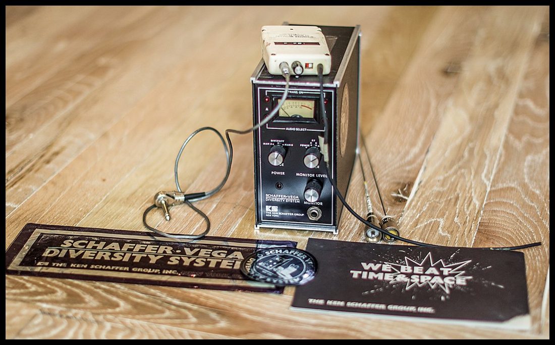
Monitoring became its own specialty. Wedges, sidefills and dedicated consoles gave each performer a mix. Wireless systems such as the Schaffer-Vega Diversity System and Vega Cordless Mike freed performers from cables, and high stage volume pushed the industry toward in-ear monitoring.
A. J. Berkhout of Delft University of Technology published the theory of wave field synthesis in the Journal of the AES in December 1988. Fraunhofer’s IOSONO system (2004) and HOLOPLOT’s matrix arrays build on it.
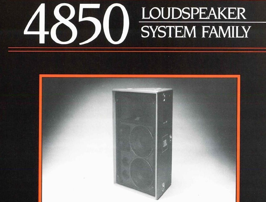
Kennedy's FOH survey describes the mid-1980s as the arrival of the factory touring box. Apogee Sound's 1985 AE-5, designed by Ken DeLoria, was a processor-driven bi-amped trapezoid with a 12-inch woofer and ferrofluid-treated HF driver; JBL's 1985 Concert Series, including the 4850, was its first factory-packaged touring trapezoid and rack line, meant to replace home-built shop boxes; and EAW's KF-850, also 1985, became the standard one-box rider requirement. Kennedy also credits Renkus-Heinz's 1989 CoEntrant horn with combining a midrange cone and HF compression driver on one concentric throat.
Plates
Documents from the era
Chronology
Milestones
Integrated touring packages mature
Standardized cabinets, racks, multicore cable, and road cases make systems faster and more repeatable.
Midas establishes a console lineage
Purpose-designed touring desks bring flexible routing and a durable control surface to front of house.
Meyer Sound is founded
John and Helen Meyer build a company around engineered loudspeaker/processor systems and measurement.
Flying becomes standard practice
Engineered rigging places clusters overhead, improving sightlines and direct-sound coverage.
speakON loudspeaker connector
Neutrik’s locking connector standardises amplifier-to-speaker wiring and meets contact-protection requirements for live parts.
Wave field synthesis
A. J. Berkhout of Delft University of Technology publishes the theory in the Journal of the AES in December 1988.
Thread · Sound in spaceTurbosound Flashlight
The prototype debuts at the Berlin Wall concert; by 1992 it covers stadiums.
Technical principle
Pattern control through horns and arrays
When multiple cabinets overlap, their phase and level relationships determine whether energy sums smoothly or produces lobes and cancellations. Defined horn patterns and deliberate splay angles let designers tile coverage with fewer destructive overlaps.
Simplified signal chain
Working vocabulary
Selected sources
- 01Huey Lewis and the News: Sound on Stage Using the Power Physics Flown Speaker System — David Scheirman, June 1985 (supplied article scans) R-e/p
- 02100 Loudspeaker Technologies that Changed Live-Sound History, Part 1 (David K. Kennedy, 6 September 2026) FOH
- 03Meyer Sound History Meyer Sound
- 04Turbosound Heritage Turbosound
- 05Midas Heritage Midas
- 06PM2000 Operating Manual Yamaha / Internet Archive
- 07It All Depends on Truss – Part 1 – The ’70s Behind the Curtain
- 0850-Year-old Lodestar Brochure on LTM Website LSi Online
- 09Why are 19-in. racks that size? EDN
- 10EIA Standard RS-310: Racks, Panels, and Associated Equipment (May 1965 scan) Electronic Industries Association (archived scan)
- 11EIA-310 rack standards explained A&J Manufacturing
- 12Power Distribution series ProSoundWeb
- 13Generators: Size Counts FOH Online
- 14Neutrik’s speakON Connector Turns 30 FOH Online
- 15Neutrik Group history Neutrik
- 16D. B. Keele Jr. Wikipedia
- 17Wave field synthesis (citing Berkhout, JAES vol. 36, 1988) Wikipedia
- 18Mixing The Cure Sound On Sound archive
- 19Turbosound announces Flashlight Mark II LSi Online
Keep going